Lab Notes
(12/28/19)
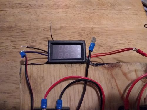
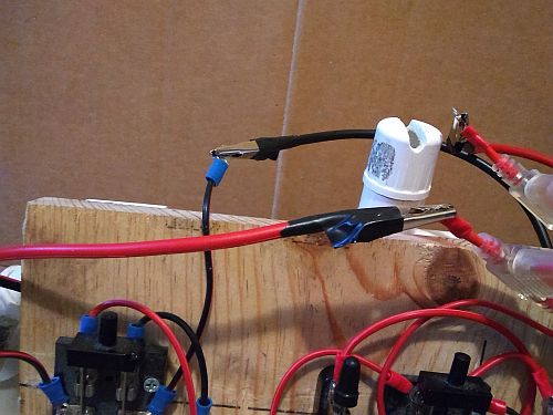
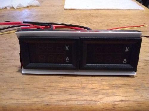
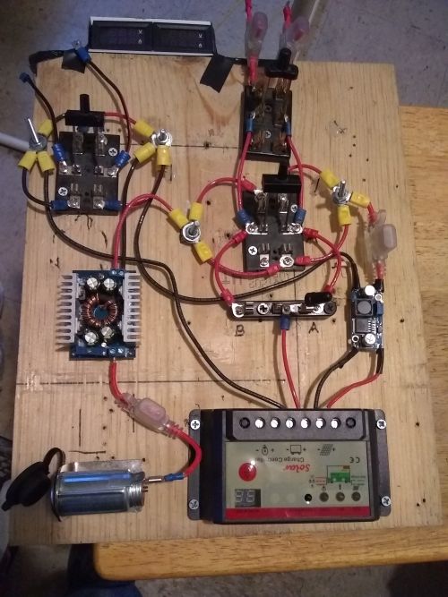
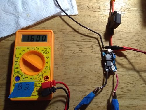
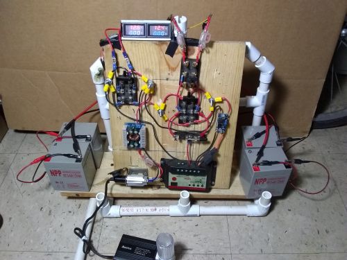
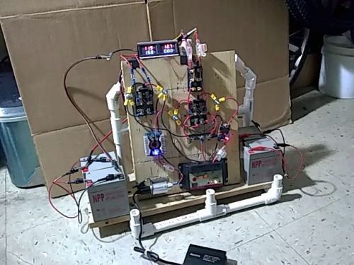
The volt-amp meter attached to the project board...
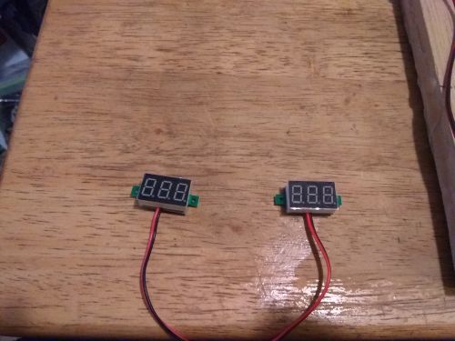
The little volt meters...
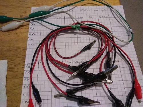
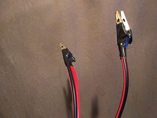
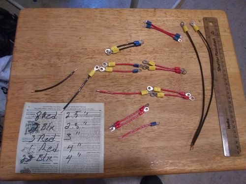
The clip leads updated with 18 gauge wire...
I hoped that the meter would be better than a sole ammeter...
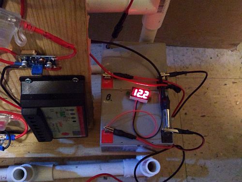
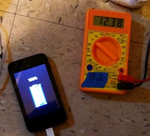
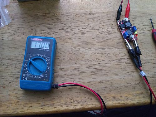
The charging battery only went up by 100mV; the volt-amp meter is too much for the system...
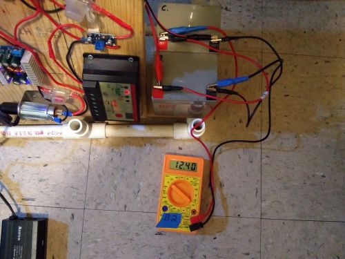
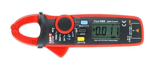
The system with no current meter does charge the 'B' side, but the AC clamp wouldn't even read AC current from the laptop power cord...
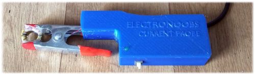
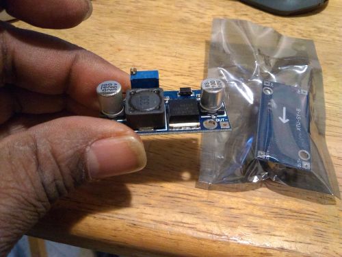
A DIY DC current meter, made by Electronoobs AKA Vladimir Espinoza, a mechanical engineer from El Salvador with a cool DIY Electronics website and YouTube channel...
(01/03/20)
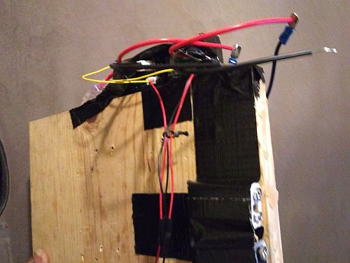
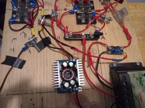
On New Year's Eve I fixed what I hoped were the last two circuit design bugs in the system - 1. a set of battery cables made with the 12 gauge wire I was saving for the 600W model, which is a bit overkill but to reduce the resistance as much as possible at the start. 2.) an unbalanced power distribution through the positive switch, caused by the crossover wires.
To fix that I came up with splitting the crossover wires and employing one-port postive busbars for the new power distribution system that isolates the two sides and balances out the positive flow. The A+ and B+ power loop wires are 2.5" long, and the A+ load tap wires are 4" each. To make room. I bobbed the negative switch crossover wires, thinking that was all I had to do there. With the bigger battery cables I thought that was the last bug in the system, so I turned back to the little V-A meters, to see if I could still avoid the current clamp...
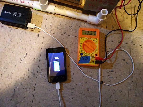
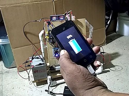
The system on Monday still charges slowly on the A-to-B side as the phone charges quickly...
Twenty minutes later, the phone is done, but the charging battery has barely moved...
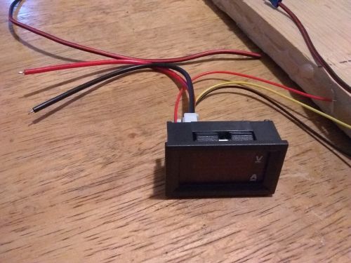
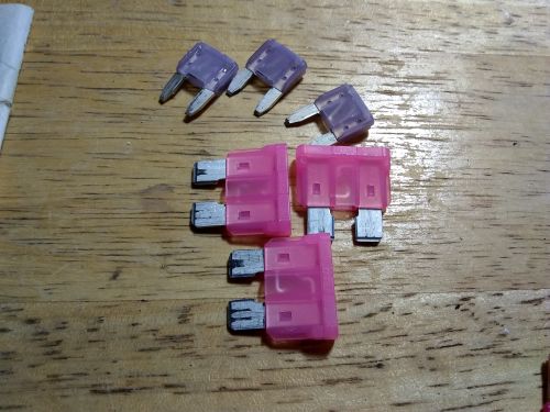
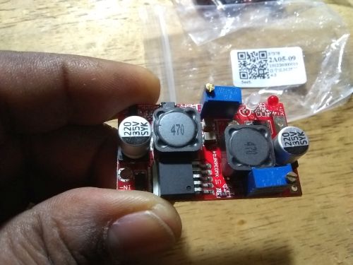
The mini V-A meters came in days early (with the different wire sets that are common nowadays)
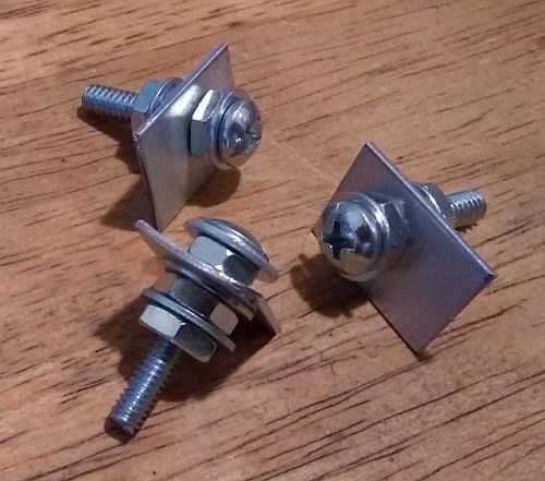
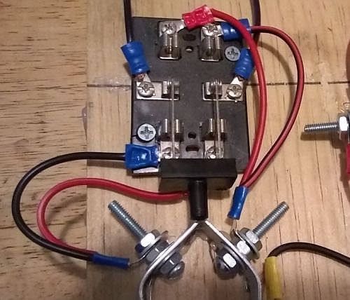
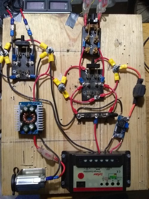
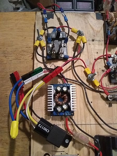
The one-port postive busbars for the power distribution system...
The new system eliminates the crossover wires and isolates the sides through mirrored connections...
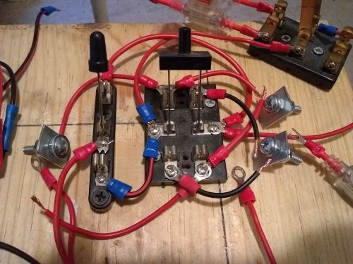
The busbars in mock-up placement...
The negative switch crossover wires shortened to make room for the busbar...
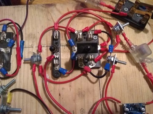
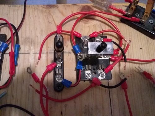
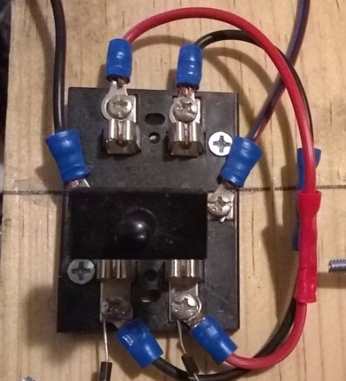
The power distribution nodes mounted and glued in place...
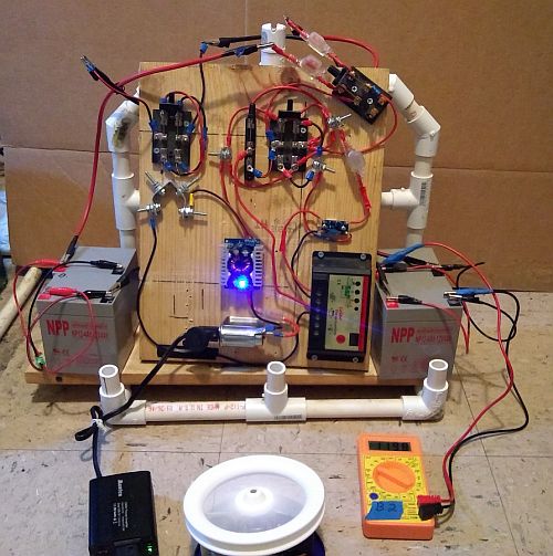
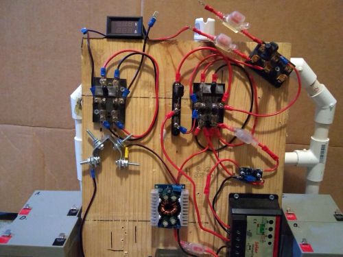
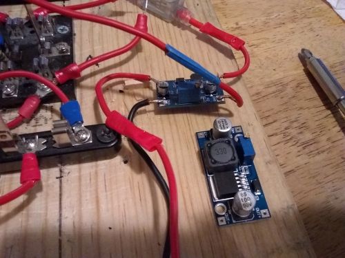
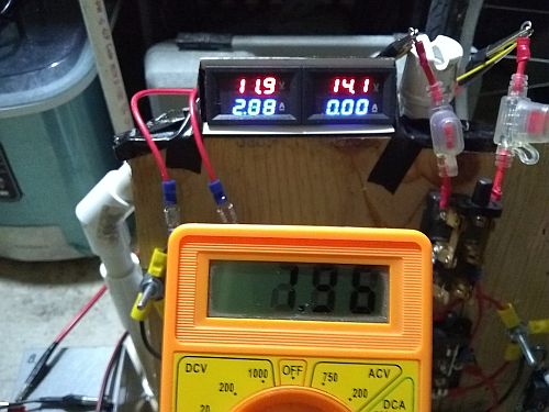
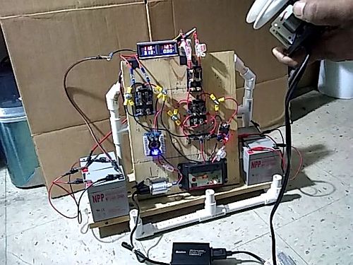
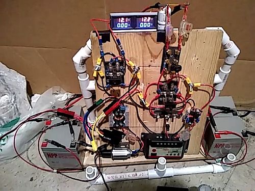
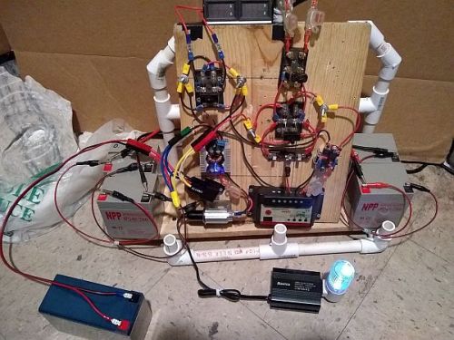
The newly evolved system running the fan motor through the A-to-B side. The rate of charge is faster with the larger load...
The fan motor/laptop load is what fried the flimsy clip leads before, so I made battery cables with the 12 gauge wire...
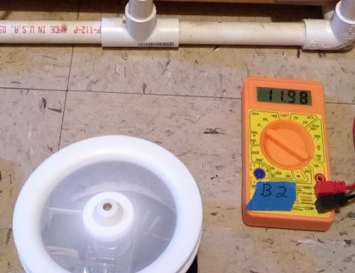
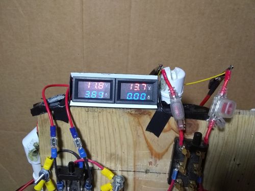
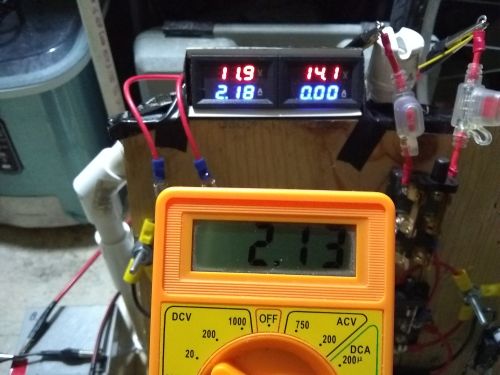
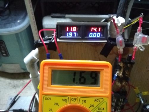
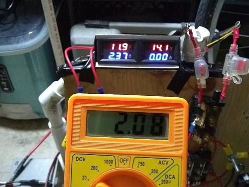
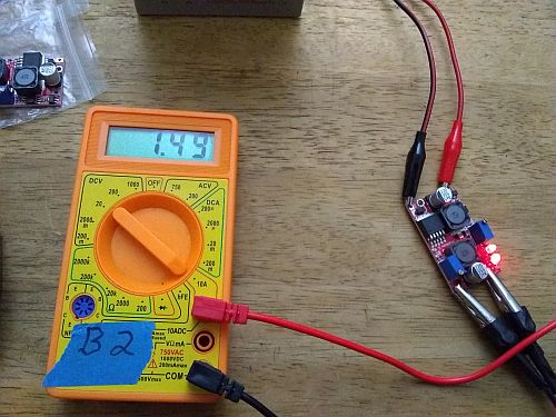
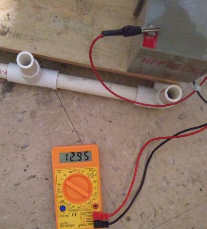
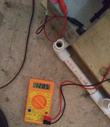
The charging battery has this reading with the system under moderate load...
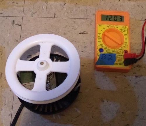
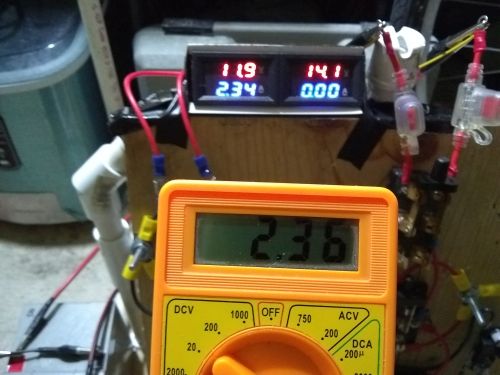
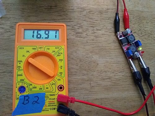
Turn the load off and half a volt returns...
With the new battery cables, hopefully that's the last bug in the device...
The AC/DC Current Clamp Meter for sale in SoCal...
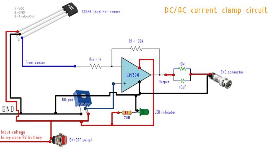
The circuit design for Electronoobs' DIY DC Current Clamp...
Maybe the Volt-Amp meters will work with the improved circuit design...
By powering the meters separately, the system might tolerate the ammeter shunt and continue charging the batteries normally...
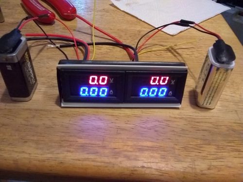
A quick and dirty mount for the 9V batteries...
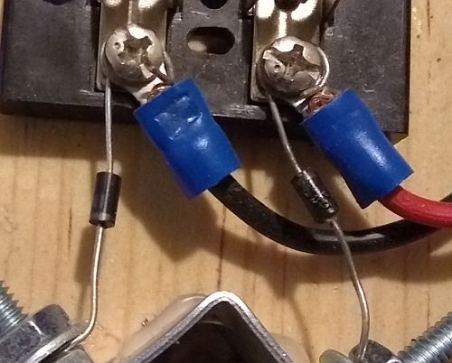
I plugged in the laptop, got a bit of clicking, disconnected A-to-B and reconnected B-to-A, the laptop brick stopped clicking, but a diode within the common ground fried under a 5 amp surge. This isn't a bug - the crossover cables on the negative side had to be modified as well...
The negative crossovers in a 'combining the negative' layout that resolves the 'splitting the positive' layout at the front end of the circuit...
I finished that part late last night with a pair of 4" wires from the common ground busbar to the separate sides. That's as far as I got, so this weekend I'll see if this long shakeout session bears fruit, or whether I still have to use a current clamp in order to get on with coefficient testing...
(01/11/20)
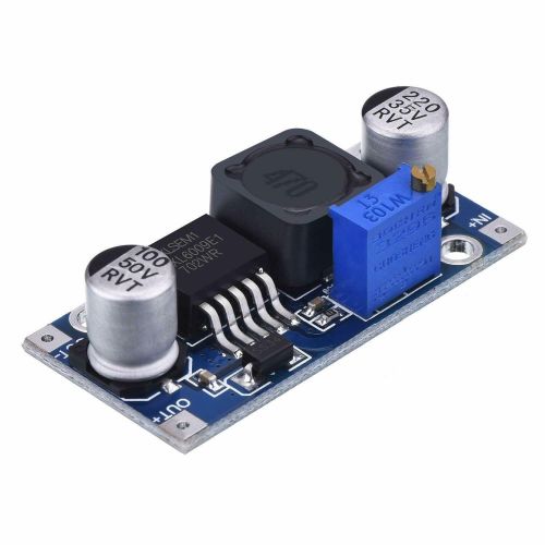
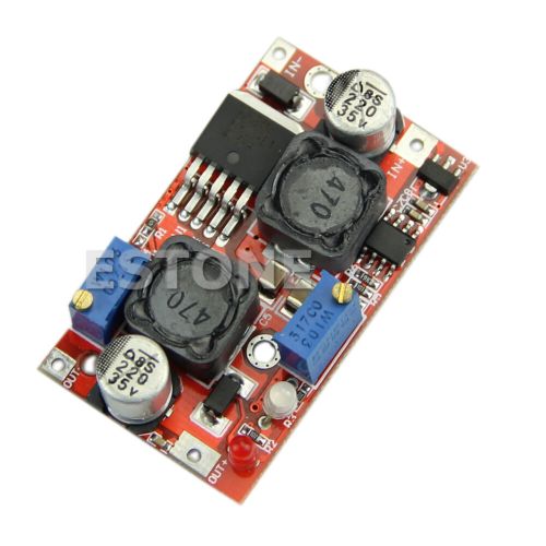
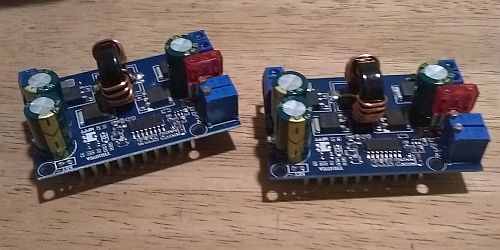
The 2A max boost converter is starting to bite now - the fan motor now jumps to 2.2A at startup, and since I need spares I decided to bump up to a 4A converter but keep the same 16V output and the same 3A fuse....
I rewired the negative switch and split the common ground busbar and copied the other distribution setup, with the ground wire from the boost-buck converter on the run side, and the charge controller battery negative wire on the charging side....
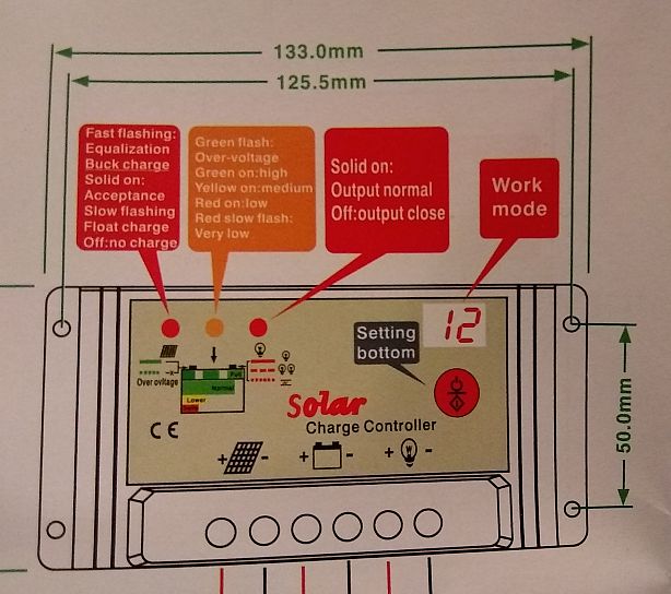
Now that the boost converter negative wire is unkinked and the solar input light is on, the data sheet from the controller comes in handy...
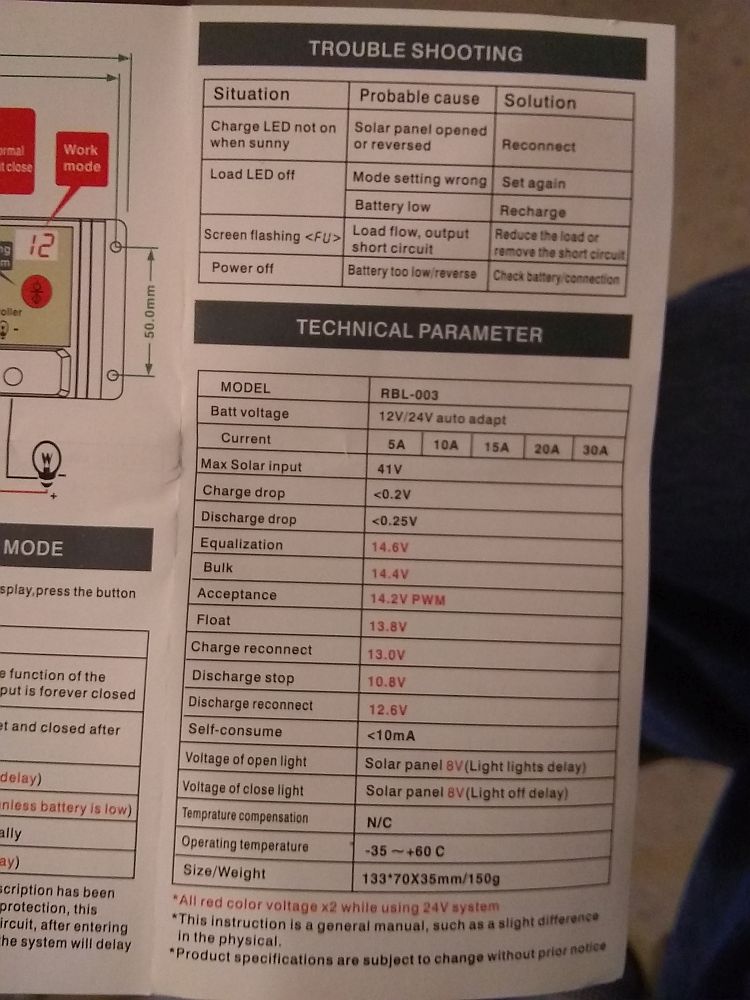
The rest of the data sheet...
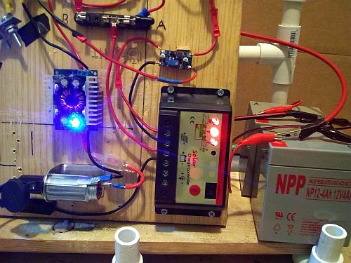
It's hard to see, but the high voltage batteries are being charged as the battery light is slowly going from red to amber, indicating that the controller is sending a full charge to the secondary battery...
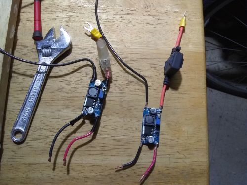
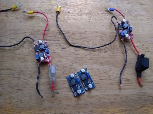
The 4A boost converter and spare...
(01/20/20)
The 100W demo power plant turned out to be simpler than I imagined, as the booster ended up being the actual last glitch...
Comparing the 2A and 4A boosters...
The 14 AWG wire sorted...
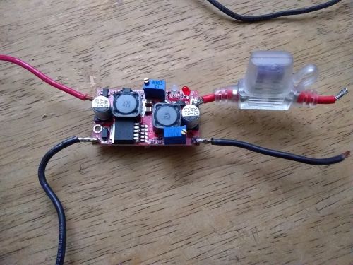
The 4a booster prepped for the circuit the first time...
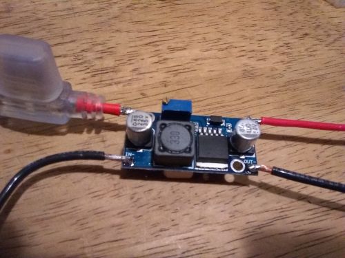
close-up...
The overhauled circuit board still in mock-up form...
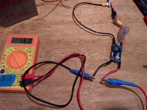
The booster is calibrated to output 16V to the charge controller...
By Sun. evening the overhaul was complete, the circuit board cleared the four-way continuity test...
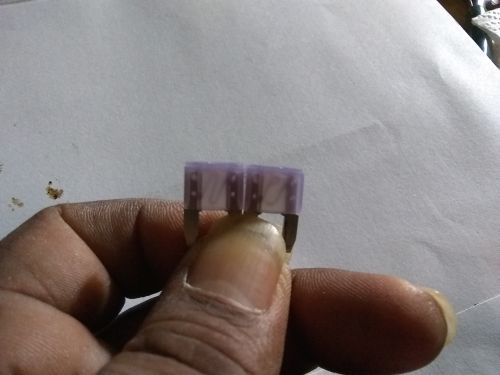
An intact and a blown 3A fuse...
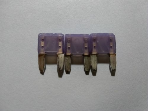
By the time the 3rd 3A fuse blew, I realized it couldn't handle the power loop...
The local auto store did sell 4A mini fuses, but only online; the only 4A blade fuses they did have were the bigger 'ATO' size, along with an inline holder...
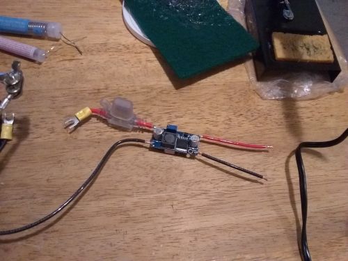
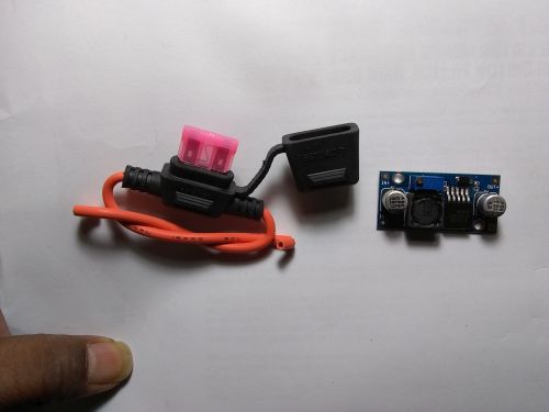
Using the other booster module, I soldered together this backup component...
Calibrating the new booster...
The first iteration of the two boosters...
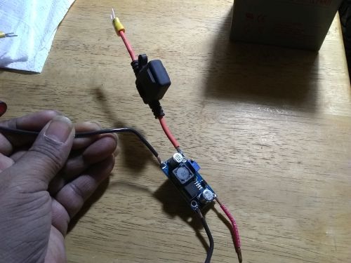
With the backup booster installed, I ran another continuity check and a shakedown run. Just like before, the circuit ran once or twice, then the 4A fuse blew - three of them too... Since I'm not running a B+ line anymore, the fuse TO the booster should copy the boost-buck converter and go AFTER the booster and complete the circuit overhaul...
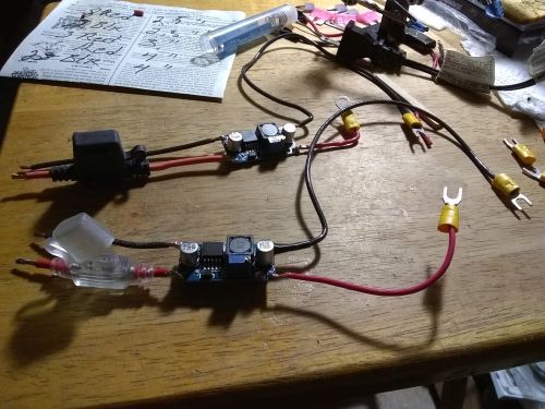
After de-soldering and re-soldering, the 4A boost coverter modules are done and ready for shakedown testing tomorrow morning - the 4A and a 3A fuse in the mini holder...
Three more blown fuses...
A before picture for the shakedown test - I had two fuses left...
Half of 3.89A, minus 300mA, is a booster current of 1.645A, more than enough to charge the battery bank...
On Fri. at eBay I found my new doohickey - a couple 30W 2A CC CV boost buck converters for $6 total, not from China but Hong Kong - and yeah, on Sat. I called the Berkeley shop to check, but they only had one size boost buck and it only put out 9V max, but I tried...
Five rapid shots within about 20 seconds of the split current reading for the system...
The current situation is damn good; my demo power plant is kicking, and until the saddle arrives, I have a couple weeks to focus on the other major project this year, getting a campervan and going mobile, that's getting its own overhaul...
(02/02/20)
Ok, while it's downtime waiting for the new part, I focused on the mobile lab-studio campervan plan. The reason why hasn't changed - the rent is too damn high and I don't wanna get stuck. And since I do have a vehicle - an old Diamondback hardtail steel MTB, built like a tank - I should actually bug out, put my stuff in storage and go Walkabout...
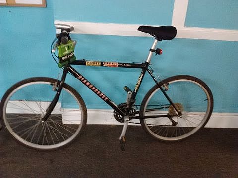
The MTB when I got it in 2016...
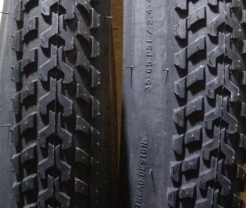
General purpose street/offroad tires. Not putting them on until after I get some riding in...
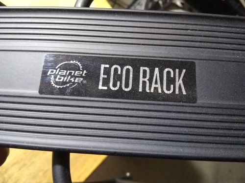
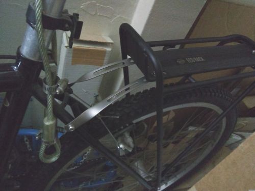
The rear rack for panniers and a cargo trailer hitch mounted on the end...
The 25W boost buck converters arrived early, so the lab is back up on Monday...
(02/08/20)
Ok, new week in the lab, working on the power plant and the bike...
Calibrating the new boost buck converters. I'm setting the output at 17V over 16V because that is the 'rated terminal voltage of the average 12V solar panel'...
I slowly set the current to 1.5A, looking for any sign of blue smoke...
Calibrating the second converter...
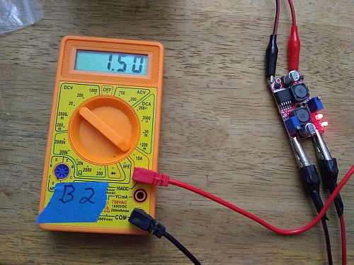
Current set, and a reminder to get another cheap multimeter...
After cleaning and resoldering my iron, I de-soldered and re-soldered the wires to the new converters...
The unit with the regular fuse holder will be installed to the board...
During the Thur. shakedown test, I read 1.5A from the run battery with just the power inverter connected...
With the phone charger connected, the current draw is 1.8A...
The fan motor at the highest setting only pumps the steady current draw up to a max of 3.2A; anything over 1.5A goes to the load taps...
With the laptop plugged in, the heavy 90W load spiked to just over 3A, then settled between 2.5-3A. No more 5-6A surges; the system is locked down and under control...
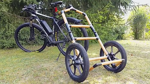
The bike trailer design, a DIY bamboo copy of the Burley Travoy trailer. While I search for bamboo, I can make a pvc mockup. Source: see YouTube and Instructable 'How to Build a Bicycle & Hiking Trailer with Bamboo - BooTec'...
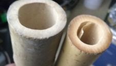
The first two bamboo poles for the trailer - about 1.5" dia., 4 ft.long. Five poles should do it...
The rear rack is sitting far enough back that I could hang a big grocery store size bag off it and it just might clear the back of my feet. Changing the depth from 15.5" to 14" should fix that too...
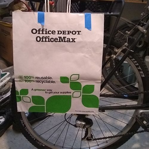
I tested it out with a big shopping bag - placing the leading edge a few inches back on the rack looks cleared of the foot path...
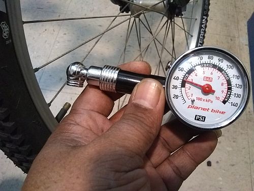
My old tire pressure gauge was busted, but the bike shop only had digital models, luckily the local REI had an analog gauge. This is in the low end of proper psi (35-65 psi). Front tire...
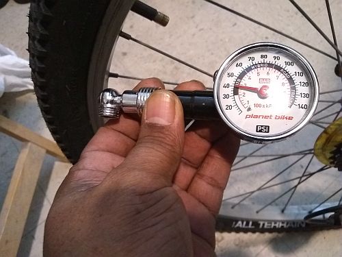
...And rear tire. The hand pump might get it up to 50 psi with lots of sweating, but on the road I could get it this far in a few minutes...
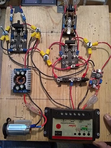
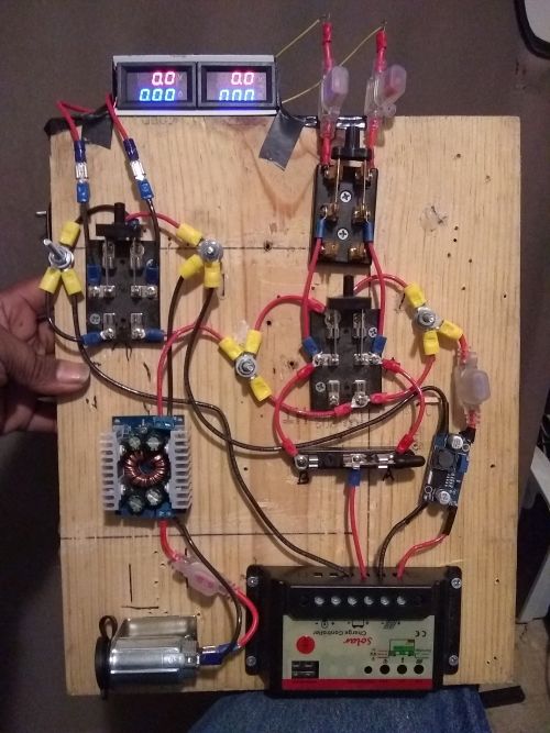
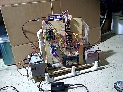
The system looks like this now - switches in the up or 'A to B' position, split positives going to the phantom 25W solar panel and the phantom 100W solar panel...
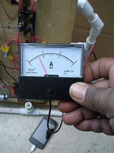
The analog ammeter connected to the output control switch reads about 700mA going into the charging battery as the run battery reads almost double the amp draw...
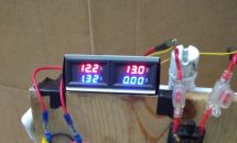
This is the voltage reading of the two batteries while the ammeter is connected...
(02/29/20)
The previous fortnight spent discovering the practical operating parameters of the device has essentially answered my questions on maintaining battery charge under a light and a heavy load, how long before a 50W solar panel is needed, and the best switch rate...
The DC transfer switch added to the board for the 12Hr test...
Still from the very beginning of the short backup switch test video, showing the night light off...
Still from the very end of the short backup switch test video, showing the night light on. The backup 12V 7Ah battery powers the inverter just fine...
Fully charged batteries for the Fri. test...
Same here, but the system doesn't like both batteries being completely full...

The A battery bank voltage levels over five hours under the laptop load. The smartphone load showed unchanged voltage levels over three hours...
(03/18/20)
Since the lab's been on hiatus waiting for another power plant component, I spent most of the past fortnight wandering the camperbike weeds to decide what kind of bike living I want to do, which determines what and how to pack for it. Meanwhile the converters came in as I began production of the episode.
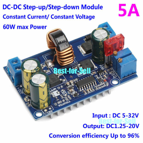
I found this 5A CC CV DC converter on sale from Hong Kong eBay and ordered two. This will work with 22Ah batteries...
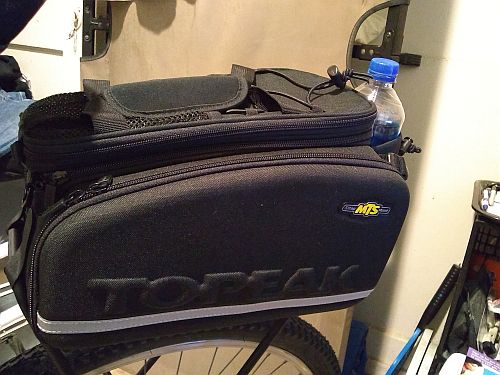
One of my bikepacking bags - a trunk bag that sits on the rear rack, instead of a seat bag...
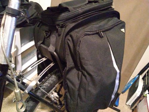
The side panels expand into panniers. The velcro straps underneath and in front attaches to the rack, and tie-downs secure the pannier bottoms to the rack frame...
The front velcro tie-downs. Total capacity of the bag is 22.6 liters/1380 cubic inches...
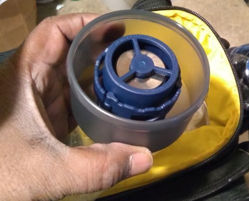
For coffee, I picked the small and lightweight GSI Coffee Rocket, a one-cup pour over unit that doesn't need a filter...
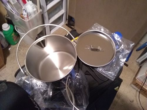
For most cooking, I just wanna boil water for instant meals or heat up canned goods, so I picked the Snow Peak Kettle No. 1 - 0.89 liters/about 30 oz. Aluminum, Japanese make...

As long as I'm taking a trailer for my sculpture gear and power plant, I can include a 5-gal. bucket and this Luggable Loo seat so I won't have to dig a cathole in the woods...
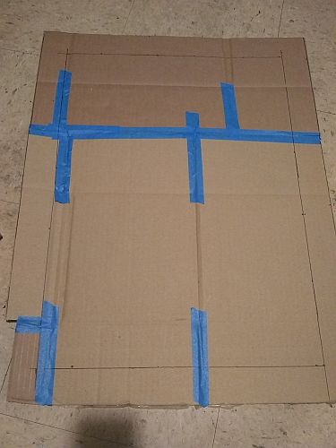
A rough cardboard mockup of the dimensions of the Schwinn Daytripper Cargo trailer - 27.00" x 23.50" outside, 23.00" x 19.50" actual cargo area minus 2" elbow room...
The 5A boost buck converters just came in. After wiping down the box it came in, my doorknobs and lock, and keychain, then washing my hands, I opened it up, took the doohickeys out, washed my hands again, then admired the components that have 10A fuses, not 5...
(04/17/20)
[Note: This page will now only feature lab notes from the current episode. Previous notes are in the Archive...]
On top of the lockdown being extended, I lost two weeks dealing with a screw up by my former bank, but anyway, I did manage to get some lab work done...
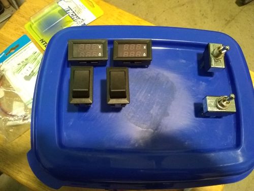
For expediancy's sake I settled on a dollar store plastic container as the enclosure for the mobile Bentez-8 power plant. The placement of meters and switches won't be cramped...
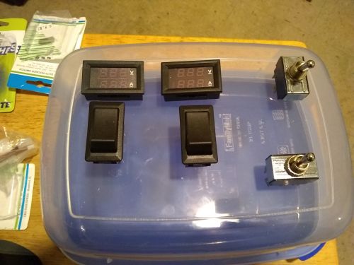
An alternate take that shows the 3.5 - 4 inch depth of the little tub. The 12V outlet doesn't have a dedicated spot yet...
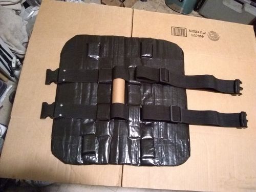
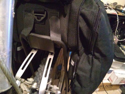
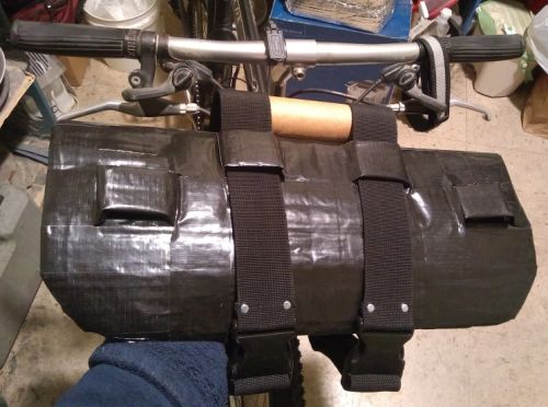
Since the REI store was closed, I couldn't go buy the handelbar harness I put in my wish list, but comparing the $100 and up models to the DIY harnesses, I decided to play off two or three different examples for design elements and made what I hope is tough, flexible, waterproof and should easily carry 10 - 15lbs. of camping gear...
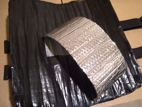
For the core I used what the hardware store had - Reflectix pipe wrap, 6 inches wide x 10-15 feet long. I cut three 18 inch long panels, covered it with two rolls of silver tape on the inside, one roll of silver and one roll of glossy black tape outside, then the belt loops (1.5 - 2 inch wide x 6 inches long Reflectix strips) were tacked down with electrical tape and one final roll of non-glossy black tape covered the outside and finished the inside. A handlebar extension bracket will help keep a loaded harness off the brake and shifter cables, once the bike store opens back up in another month, I hope...
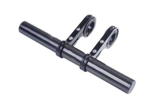
A typical handlebar extension bracket, this model sold by Walmart, which makes the harness more like a sling. With the two belts it weighs a little over 2 lbs...
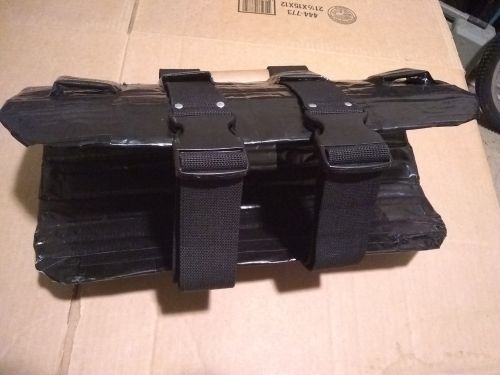
It's just big enough to hold my bikepacking sleeping bag, a pad, couple tarps...
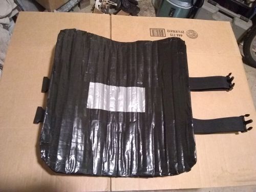
The inside. I bought duct tape for the DIY panniers project before I got the rack bag (see last episode)...
The extension bracket should hold the bag about 3 inches out front. So far, total cost is around $45...
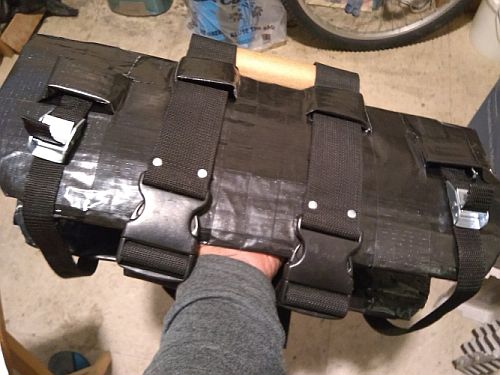
The dollar store had these rudimentary ratchet straps that completes the sling...
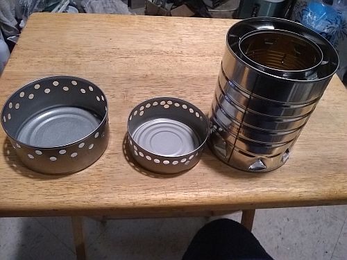
These are my camp stoves: two very basic tuna can type alcohol stoves (10 oz. and 5 oz.), and my mini rocket backup stove for burning wood...
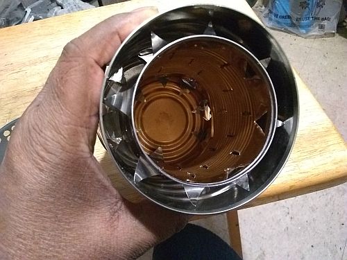
This wood-burner, though bulky, is even smaller than the YouTube video model I copied, but it should provide a decent one-person campfire...
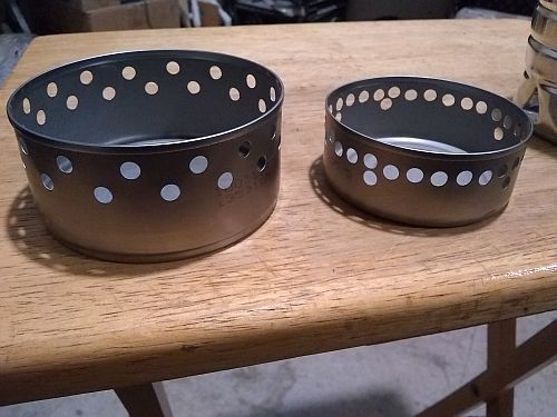
According to a few YouTube reviews of alcohol stove fuels, Heet in the yellow bottle is good and fast for outdoor use, but only Everclear should be used indoors (and apparently denatured alcohol stinks as it burns). The 10 oz. can stove is too big for the kettle, but it will work with a 7 - 10 in. skillet for occasional eggs and bakey...
As a fall back cargo trailer, I'm copying a bike hack from a 2012 bike forum page found via Internet Archive's Wayback Machine - 'Utility Cart Bike Trailer Hack'...
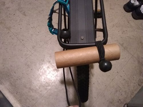
This is the inspiration from the old bikehacks.com forum page - a granny cart strapped to a bike rear rack using bungee cords with bangle ends...
A closer look at the simple hitch...
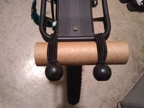
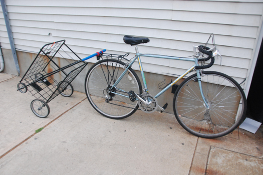
Even though the rack is a different design, in mockup the arrangement seems to handle pitch, roll and yaw...
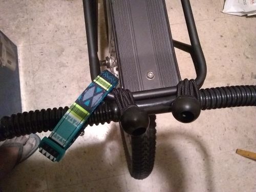
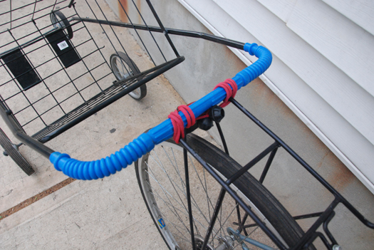
With my cart attached, the bungee hitch allows a little bit of side play, but a little duct tape on the ends of the plastic grip should fix that. The dog collar serves as a safety strap; another would be better...
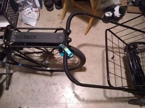
There's just enough room on the rack for the trunk bag to fit with the water bottle slightly nudging the bungee hitch bangles. This is a last ditch cargo trailer in case I can't get the Schwinn Daytripper, since it has a capacity of 60 lbs. or so. But, in 8 yrs., nobody else copied this method and no follow up from the original poster, so, I really need a more solid hitch using eyebolts and clamps...
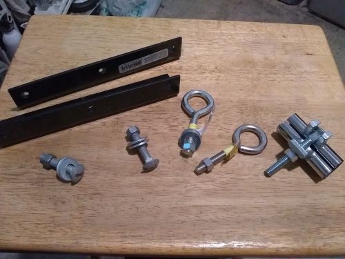
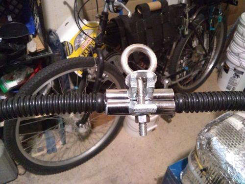
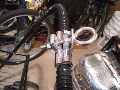
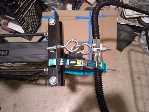
A few days later, a bit of essential business - my first try sorting parts from the hardware store. From R to L: a 3/8" single bolt pipe repair clamp; two 3/8" eyebolts, two 3/8" x 2" bolts, nuts, washers; two heavy duty house grade 6-hole corner braces...
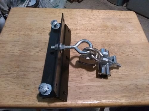
The mockup of the trailer hitch with my master lock hitch pin, as suggested by more than one bike forum..
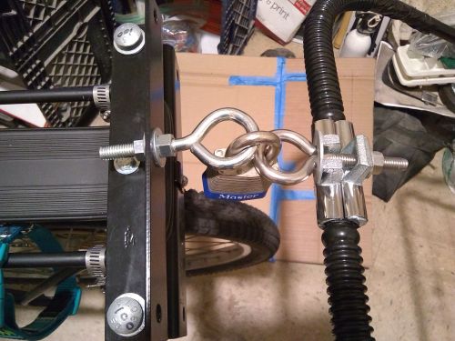
The rack mount in place, sandwiching the rack's butt. There were shorter braces at the hardware store, but this size should transfer less stress to the rack itself...
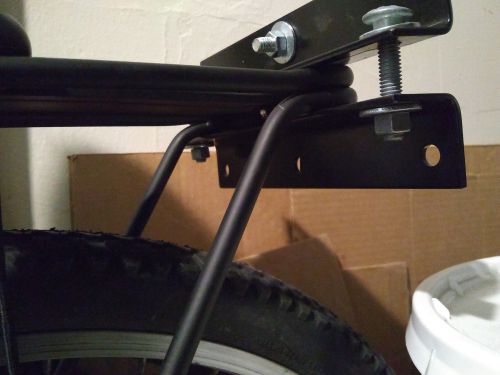
The lower brace is well above rear fender height. Its two center holes bolt to the rack...
Something needs to go between the rack and the rails...
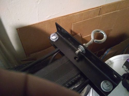
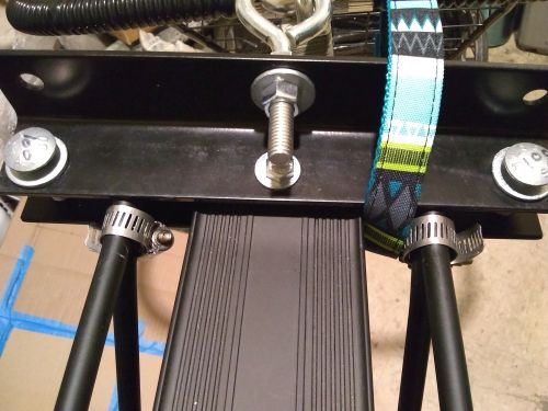
I duct taped the ends of the plastic handhold and removed the center part with a box cutter, then added it as a shim...
Much better than the bangle bungee hitch... I went back to the hardware store for nylon lock nuts for the eyebolts, in case of vibration, but the thread didn't match, so if needed I'll try lock washers...
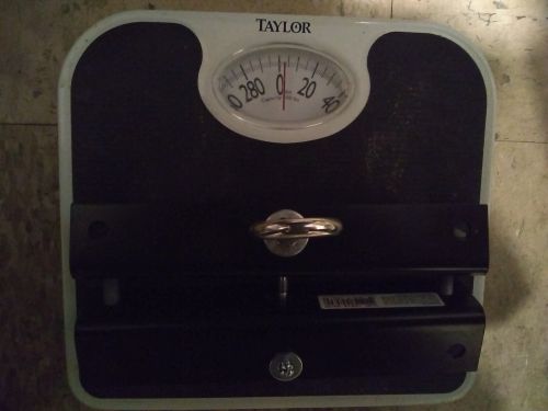
The rack mount's total weight turned out to be less than 5 lbs...

Just 3 lbs., not enough to impact the planned weight of the panniers...
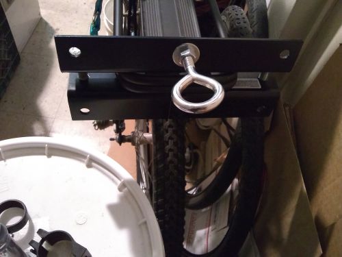
I assembled the rack mount, tightened the bolts alternately, added the hose clamps to lock it in place laterally...
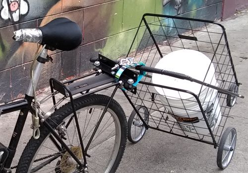
The dog collar safety strap just fits the hitch...
Front view of the installed rack mount...
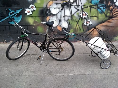
On Thursday around Noon I brought the bike and trailer out and ran a 10 minute test ride. The cart rattled a bit from the light dummy load, as expected, but otherwise, 5x5...
A reminder that I have to replace my uglified city bike seat for a travel-touring seat...